Multi-function Tester
Instructions
1. Introduction to the tester body Interface
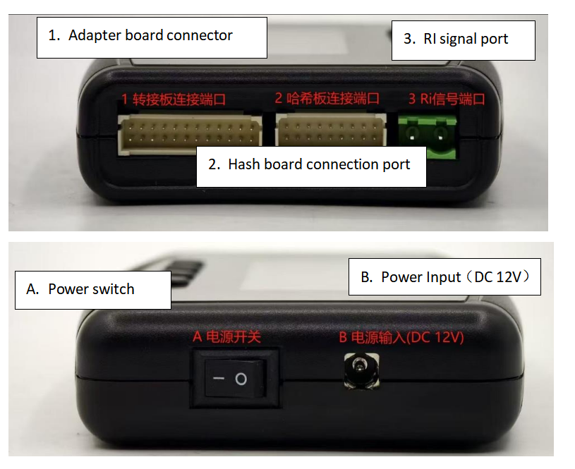
1. Adapter board connection port 2. Hash board connection port 3. RI signal return interface
A. Power switch
B. Power input (12VDC)
2: Button function instructions
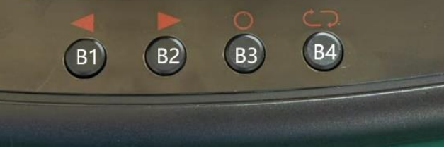
B1, function selection left B2, function selection right
B3, confirm
B4, return three: function introduction
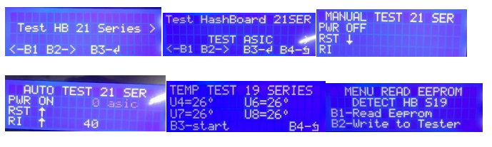
1. After the test stand is turned on, the Ant 17/19/21 series models will automatically identify the hash board and enter the test. If you do not enter the test interface, you need to manually select the model to enter the corresponding model test.
2. After entering the test interface, press the B2 button (right button) to select the test mode: TEST ASIC (hash board chip quantity test)/TEST TEMP (hash board temperature test)/REPAIR EEPROM (hash board EEPROM editing).
3. After selecting the test mode, press the confirmation button to start the test.
4. Press B1 (left button) to select RI multiple tests, press B2 (right button) to select single test, and press OK to enter RST multiple tests.
5. After the PWR test, the number of chips will be displayed. For example, if the S19pro has 110 chips on the whole board, 110asic will be displayed. After entering the RI, RST test mode for multiple times, the number after RI will count down from 99 and stop after counting to 1. After the test, press the return key to return to the main interface. 6. TEST TEMP (temperature test), press OK to test the temperature of the corresponding temperature control chip. 7. REPAIR EEPROM (computing board EEPROM editing), press B3 (confirm key) to enter, press B1 (left key) to copy the useful EEPROM chip data, and press B2 (right key) to write the computing board EEPROM chip to be repaired.
Four: Fan and power supply test
1. After connecting the fan test adapter board, select "FAN TEST" on the main interface of the test stand. Note! The fan test requires a separate power supply. The tester does not supply power to the fan. After the adapter board is inserted, the test stand automatically enters the fan test mode. Press the OK button to turn on the fan switch, and press the left and right buttons to test the fan speed and frequency respectively.
2. The power source needs to turn off the test stand first, then press and hold the test stand B3 (confirmation button) to turn on the test stand, and enter the power supply test mode after turning on. Press the left and right buttons to select the power supply model, and then press the confirmation button to enter the test. If the power supply is damaged or the data interface is in poor contact, "NO PSU" will be displayed. If the power supply is normal, press the left and right buttons to adjust the voltage output by the power supply, indicating that the power supply is operating normally.
Appendix: Interface description of the adapter board and fan and power supply test interface
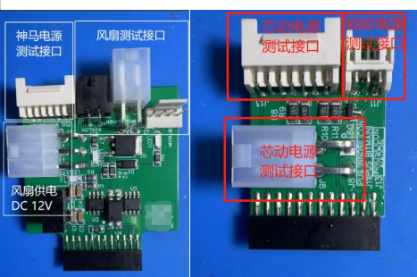
Adapter board interface description

Fan test interface
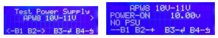
Power test interface

 Favorites
 History
 65042.8USD
 47.75USD
 1934.88USD
 0.03USD
 7.08USD
 574.26USD
 0.02USD
 75.83USD
 0.04USD
 1.11USD
 0.07USD